
LED Warning Light Technical Guide: Mounting, Voltage, IP Rating and Lens Selection
Short answer: A LED Warning Light is correctly specified when four parameters agree with the vehicle: the operating voltage range covers every vehicle in the fleet, the mounting method matches the real installation surface and clearance, the IP rating matches the cleaning and exposure regime at that position, and the lens material matches the mechanical and chemical environment. The four are linked. A high IP rating is only achieved with the correct grommet and mounting method, and a wide voltage range only helps if the control circuit can carry the current.
This guide explains each parameter against documented product data from SIGROCK, a Ningbo-based manufacturer of vehicle warning and signaling lights founded in 2018, and shows how each choice maps to actual operating conditions: mixed 12 V / 24 V fleets, grille and license-plate mounting positions, high-pressure wash routines, and lens exposure to debris, cleaning agents and UV.
Problem Definition: Why Warning Light Failures Are Usually Specification Failures
Most warning light complaints that reach a supplier are not optical complaints. They are fit complaints: a unit that stopped working after a winter of road spray, a beacon that cracked after a wash-down, a lightbar that dimmed when a second appliance was switched on, or a hideaway light that never sealed because the panel behind it was curved.
Those are specification failures, and they appear in predictable patterns:
- Voltage mismatch. A unit wired into a 24 V circuit on the assumption that all units are 12 V, or a wide-range unit installed without checking current draw at 12 V.
- Mounting mismatch. A bracket design used on a surface that flexes, a magnetic base used where permanent fastening was intended, or a flush-mount body fitted into a panel that is too thin to compress the grommet.
- IP mismatch. A unit rated for temporary immersion installed where the depot uses high-pressure, high-temperature washing, or a low-mounted unit specified on price rather than exposure.
- Lens mismatch. A lens material chosen without confirming compatibility with the cleaning chemicals actually used, or without checking how the lens behaves under impact from road debris.
The practical consequence is that warning light selection should be handled as a small engineering exercise, not as a catalogue lookup. The rest of this guide sets out that exercise in the order a project usually runs: electrical system first, then installation position, then environmental protection, then lens and optics.
Industry Background: Why These Four Parameters Sit Inside Regulation
Vehicle warning lights are specified against regulatory frameworks that treat performance, electromagnetic behaviour and installation as separate questions. That separation matters because a product can be compliant on one axis and unsuitable on another.
- ECE R65 addresses the photometric performance of warning lights for motor vehicles in ECE jurisdictions. Public technical commentary on the regulation describes Class 2 devices as using dual-level intensity control, operating at maximum brightness in daylight and dimming at night; buyers should confirm class and current revision with the supplier and with the approval documentation rather than from summary articles.
- ECE R10 addresses electromagnetic compatibility (EMC) approval for applicable vehicles and electrical or electronic components. It deals with emissions and immunity, and it does not replace photometric or installation approvals.
- SAE J595 is a recommended practice covering directional, single-colour, flashing optical warning devices used on authorized emergency, maintenance and service vehicles. The 2021 edition is documented as providing design guidelines, test procedure references and performance requirements; earlier editions exist and should not be merged with the current edition when writing a specification.
Market context supports the direction of travel rather than the selection decision itself. A Lucintel report summary published in 2026 projects the global emergency warning light market growing at a compound annual growth rate of 3.6% from 2025 to 2031, which is consistent with a mature, regulation-driven category where specification quality — not novelty — decides repeat orders.
Parameter 1: Operating Voltage and Current Draw
Operating voltage is the first filter because it decides whether a single part number can serve a mixed fleet. All four SIGROCK warning light families covered in this guide are documented with a 10–33 V DC operating range: the E6 warning light module, the T43 hideaway warning light, the BH18 LED beacon and the LB01 warning lightbar. That range covers both 12 V and 24 V vehicle systems without a separate variant.
Current draw is the part buyers skip. The same 10–33 V DC family contains very different loads:
- E6 module: maximum 0.66 A at 12 V and 0.33 A at 24 V.
- T43 hideaway: maximum 0.3 A at 12 V and 0.15 A at 24 V.
- BH18 beacon: 2.2 A at 12 V and 1.2 A at 24 V.
- LB01 lightbar: documented as 76 W at 600 mm, 92 W at 800 mm, 108 W at 1000 mm, and 124 W at 1200 mm, 1400 mm and 1600 mm.
Two engineering consequences follow. First, the 12 V current figure is the worst case and should be used for fuse and cable sizing even on a 24 V fleet, because the same vehicle may be jump-started or serviced on a 12 V circuit. Second, the control device has to be checked against the total load. The SC7X controller is documented with a 10–30 V DC input, a 40 A maximum current output, a 40 A fuse rating, and either 2 × 10 A or 4 × 5 A outputs, wired with AWG 14 red and AWG 16 black input conductors and AWG 16 or AWG 18 output conductors.
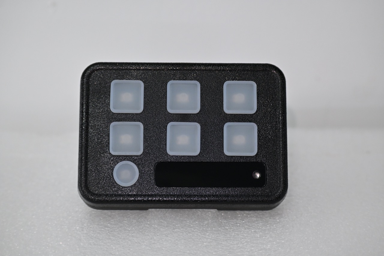
Note the asymmetry: the warning lights accept 10–33 V DC, while the SC7X controller is documented at 10–30 V DC. On vehicles with wide charging-system variation, that difference belongs in the specification review, and the controller should be treated as the bounding component in the circuit.
Voltage selection rule
- Confirm the vehicle system voltage and whether the fleet is mixed 12 V and 24 V.
- Require a documented operating range that covers both, not a nominal 12 V rating.
- Record the maximum current at 12 V for every model in the bill of materials.
- Sum the load per output channel and compare it with the controller's documented output configuration and fuse rating.
- Confirm connector type and cable length against the routing distance before ordering.
Parameter 2: Mounting Type and Installation Surface
Mounting is where most installation defects originate, because the mounting method determines whether the product's sealing and optical aim survive contact with the vehicle. The documented mounting options across the SIGROCK range are deliberately different, and each maps to a different installation condition.
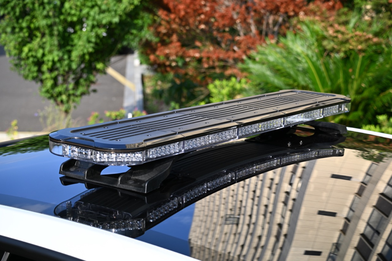
- Bracket mount — LB01 lightbar, E6 module. Suited to roof-level or structural bracket positions where the bar or module is fixed to a purpose-made carrier.
- Bolts, DIN or magnetic mount — BH18 beacon. A single beacon body covering permanent bolted installation, DIN mounting and temporary magnetic deployment.
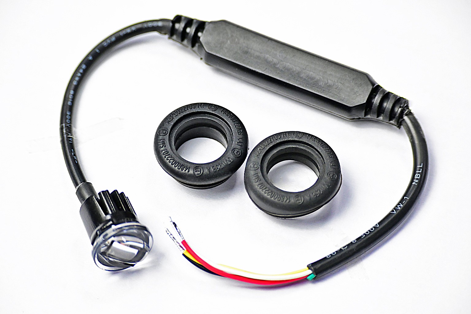
- Flush mount and tube flush mount — T43 hideaway. For discreet integration into body panels, with a black rubber grommet documented as part of the assembly.
- Surface mount and bracket mount — E6 module. For flat surfaces and bracket kits where a slim 7 mm profile must sit close to the panel.
- 3M VHB, suction cup bracket and 3M surface-mount VHB sticker — SC7X controller. For in-cab mounting where drilling is undesirable.

Three checks decide whether a mounting method is right for a given vehicle:
- Surface and thickness. Flush mounting compresses a grommet against the panel. If the panel is thin, curved or double-skinned, the compression is uneven and the seal becomes the weak point of the whole installation.
- Clearance and access. The E6 is documented at 118 × 25 × 7 mm, which allows installation in shallow recesses, but the cable exit still needs space and strain relief behind the panel.
- Vibration and serviceability. High-vibration environments are a normal operating condition for utility, construction and road maintenance vehicles. Fasteners, brackets and grommets should be selected so the unit can be removed for service without damaging the panel.
Magnetic mounting is best treated as a deployment option rather than a permanent fitment: it is useful where a beacon must move between vehicles, while permanent fleet fitment normally calls for the bolted or DIN configuration of the same beacon body.
Parameter 3: IP Rating — IP67 and IP69K Mapped to Real Cleaning Regimes
IP ratings classify protection against solid-object and water ingress under specified test conditions. The two ratings that appear most often on vehicle warning lights test different things:
- IP67 covers dust protection and temporary immersion under the specified test conditions.
- IP69K covers dust protection and high-pressure, high-temperature water-jet exposure under its applicable test standard.
Neither rating alone guarantees suitability for every environment. The correct question is not "which number is higher" but "which exposure does this mounting position actually see".
| Exposure at the mounting position | What drives the requirement | Documented example in the SIGROCK range |
|---|---|---|
| Roof-level bracket position, rain and road spray, no direct jet cleaning | Dust and water ingress from weather; cable entry protected | LB01 warning lightbar — IP65 |
| In-cab controller position | Spill and condensation resistance | SC7X controller — IP67 |
| Grille, body panel or license-plate position exposed to spray, mud and depot washing | Dust, mud, direct water jets, washing chemicals | E6 module — IP67/IP69K; T43 hideaway — IP67/IP69K; BH18 beacon — IP67, IP69K |
The practical reading is straightforward. The LB01 lightbar is documented at IP65 while the E6, T43 and BH18 are documented at IP67/IP69K. Where a light sits low on the vehicle, or where the operator washes equipment with a high-pressure lance at close range, the documented IP69K configuration is the one to specify. Where the unit sits at roof level and is washed incidentally, the requirement is different.
An IP rating is also a property of the installed assembly, not only of the light. The T43 relies on a black rubber grommet; a grommet that is pinched, under-compressed on a thin panel, or fitted to a damaged cut-out will leak regardless of the rating on the datasheet. Cable entries, connectors and any additional holes drilled during installation belong in the same sealing review.
Parameter 4: Lens Material and Lens Configuration
The lens is the only part of a warning light that faces the environment directly, so lens selection is a mechanical decision before it is an optical one.
PC lens: what the documented products specify
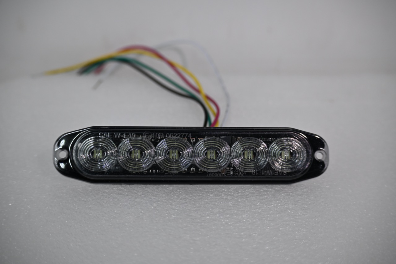
All four warning light families covered here specify a PC (polycarbonate) lens: the E6 module, the T43 hideaway, the BH18 beacon and the LB01 lightbar. On the LB01 and BH18 the documented material set is PC lens with aluminium housing; the T43 is documented as PC, aluminium and rubber.
That combination is the basis of the mechanical protection argument. A rigid PC lens over the LED and optical assembly shields the light source from road debris, and the aluminium housing carries the structural load, so the lens is not also acting as the mounting structure. On the T43, the rubber grommet absorbs the interface between the light and the body panel, which is what allows a flush-mounted unit to survive panel flex without transferring that movement to the lens.
Lens selection should also be checked against the cleaning routine. Whatever material is chosen, confirm compatibility with the actual cleaning agents used in the depot, and confirm whether the lens colour specified — clear, smoked, amber, blue or red — is available in the certification configuration required for that market.
PC versus silicone: how to evaluate the alternative
Silicone and other flexible lens materials appear in some warning light designs on the market. The supplied documentation for these four SIGROCK families specifies PC, so a project that requires a flexible lens material should be treated as a configuration question rather than a catalogue question. Ask the supplier for four items before comparing:
- Material data sheet for the exact lens, not the product family.
- UV exposure data, because high UV exposure is a normal operating condition for roof-mounted equipment.
- Cleaning-agent compatibility, tested against the chemicals your depots actually use.
- An IP test report for the specific lens and housing configuration, since the lens is part of the sealed assembly.
Compare like with like. A lens material claim without the corresponding IP and UV evidence cannot be used to justify a specification change, and the reverse is also true: a PC lens with documented IP67/IP69K protection and a defined housing material is a complete, auditable specification, which is what a procurement file needs.
Lens and optics belong together
Lens selection cannot be separated from optical design. The E6 uses a Fresnel optical design; the T43 and LB01 are documented with hybrid optical designs. Optical architecture affects how light is distributed across the intended coverage area, which is why the specification should record the optical design alongside the lens material, the lens colour and the required certification class. Changing one without reviewing the others is how a compliant product becomes a non-compliant installation.
Step-by-Step: Building a Warning Light Specification in 8 Steps
- Map the electrical system. List every vehicle type in the fleet, its system voltage, and whether 12 V and 24 V vehicles will share the same part number. Confirm the light's operating range covers both.
- Calculate the load. Record maximum current at 12 V per model, sum per output channel, and compare with the controller's documented output configuration, maximum output and fuse rating.
- Define the mounting position. Decide between bracket, surface, flush, tube flush, DIN, bolted or magnetic mounting, and check panel thickness, curvature, clearance and cable routing at that exact position.
- Set the IP requirement from the cleaning regime. Establish how the vehicle is washed, at what pressure and proximity, and whether the position is high or low on the body. Specify IP67 or IP69K accordingly, and confirm the grommet or cable entry is part of the sealed assembly.
- Select lens material, lens colour and optical design together. Record PC or alternative material, the lens colour, and whether the optical design is Fresnel or hybrid.
- Fix the regulatory set per market and per function. European projects typically require ECE R65 for warning performance and ECE R10 for EMC; US projects reference SAE J595; additional requirements such as ECE R148, CE or RoHS may apply depending on the product and market.
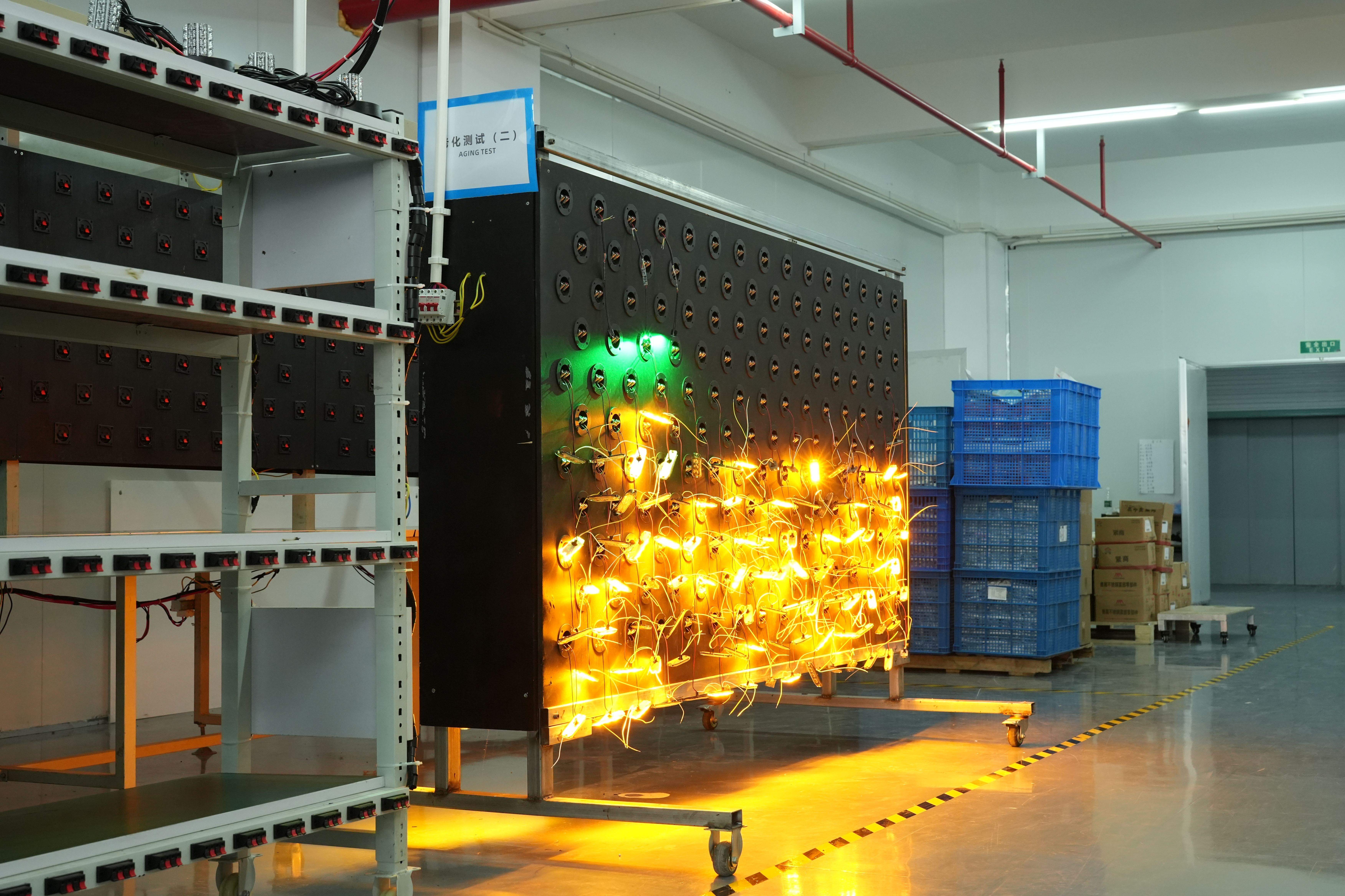
- Validate on the vehicle with a sample. Test the sample in the real mounting position, including a wash cycle, a vibration cycle and a full function test of every flash pattern and colour configuration.
- Freeze the specification and archive the evidence. Certificate numbers, test reports, wiring diagram, mounting instructions and the final bill of materials should be filed with the purchase order.
Use Cases: Mapping Parameter Sets to Vehicle Scenarios
The same four parameters produce different answers depending on the vehicle. The scenarios below use documented product configurations.
Police vehicles and emergency response
Emergency and public safety applications — police vehicles, fire trucks and ambulances — combine low-light operation with high-visibility warning requirements and, in Europe, ECE R65 and ECE R10 certification requirements. The BH18 beacon is documented with ECE R10, ECE R65 Class 2 and SAE J595 Class 1 certification, 18 LEDs at 3 W each, 10 selectable flash patterns and 2.2 A draw at 12 V. The E6 module is available with ECE R65 Class 2, SAE J595 Class 1 and R10 options depending on configuration, in a 118 × 25 × 7 mm body that suits shallow mounting positions.
Road maintenance and traffic management
Road maintenance and traffic management vehicles need traffic guidance at a distance plus durability in dust, mud and wash-down conditions. The LB01 lightbar is documented at 600 mm to 1600 mm length and 40.5 mm height, with 78 to 198 LEDs at 1 W depending on length, 10 selectable flash patterns and ECE R65 and R10 certification. For low or discreet positions on the same vehicle, the T43 hideaway — IP67/IP69K, 14 flash patterns, flush or tube flush mount — covers positions where a lightbar cannot be installed.
Utility, tow and service vehicles
Utility and service vehicles usually have limited installation space and mixed duty cycles. The T43 is documented as a 3/4-inch (19 mm) compact hideaway light combining warning and position lighting functions, suitable for 12 V and 24 V systems, which allows one part number to cover a mixed fleet. Its documented certifications include ECE R65, R148, R10, RoHS and CE.
Construction and industrial vehicles
Construction sites combine dust, vibration and temporary deployment. The BH18's documented mounting options — bolts, DIN or magnetic — let the same beacon body serve a permanently fitted machine and a beacon that moves between units, while the IP67/IP69K rating and −30 °C to +70 °C operating range cover the documented exposure conditions.
Comparison Table: Documented Parameters Across Four Warning Light Families
The table below uses only documented specifications for the four SIGROCK warning light families discussed in this guide. It is a parameter comparison for specification purposes, not a ranking.
| Parameter | E6 warning light module | T43 hideaway warning light | BH18 LED beacon | LB01 warning lightbar |
|---|---|---|---|---|
| Form factor | Ultra-slim module, 118 × 25 × 7 mm | Compact 3/4-inch (19 mm) hideaway | Rotating LED beacon, single or dual configuration | Full-size lightbar, 600–1600 mm × 40.5 mm |
| Operating voltage | 10–33 V DC | 10–33 V DC | 10–33 V DC | 10–33 V DC |
| Maximum current | 0.66 A @ 12 V / 0.33 A @ 24 V | 0.3 A @ 12 V / 0.15 A @ 24 V | 2.2 A @ 12 V / 1.2 A @ 24 V | 76–124 W depending on length |
| Light source | 36 / 12 / 18 LEDs at 3 W each | 5 W × 1 pc plus 0.2 W × 2 pcs | 3 W × 18 pcs | 1 W LEDs, 78–198 pcs by length |
| Optical design | Fresnel | Hybrid | — | Hybrid |
| Lens material | PC | PC | PC | PC |
| Mounting | Surface mount / bracket mount | Flush mount / tube flush mount, rubber grommet | Bolts, DIN or magnetic | Bracket mount |
| Ingress protection | IP67/IP69K | IP67/IP69K | IP67, IP69K | IP65 |
| Operating temperature | −30 °C to +70 °C | −30 °C to +70 °C | −30 °C to +70 °C | −30 °C to +70 °C |
| Certification (documented) | ECE R65 Class 2 / SAE J595 Class 1 / R10 options | ECE R65, R148, R10, RoHS, CE | ECE R10, ECE R65 Class 2, SAE J595 Class 1 | ECE R65, R10 |
| Warranty | 3 years | 3 years | 3 years | 3 years |
The SC7X controller, used to switch and program these lights, is documented separately: 100 × 70 × 20 mm aluminium housing, seven buttons with momentary or ON/OFF modes, automatic night-time backlight dimming, 10–30 V DC input, 40 A maximum output, 2 × 10 A or 4 × 5 A outputs, 40 A fuse, 300 mm cable harness, IP67 and a 2-year warranty.
FAQ
What certifications should a Chinese ECE R65 and R10 LED warning light manufacturer supply for police vehicle projects?
For European police vehicle projects, request model-specific evidence of two separate approvals: ECE R65 for warning light photometric performance and ECE R10 for electromagnetic compatibility. They are distinct approvals and one does not imply the other. For US projects, SAE J595 is the relevant recommended practice for directional flashing warning devices, and the current edition should be confirmed before it is written into a specification. SIGROCK's documented product certifications include ECE R10 and ECE R65 Class 2 plus SAE J595 Class 1 on the BH18 beacon, ECE R65, R148, R10, RoHS and CE on the T43 hideaway, ECE R65 and R10 on the LB01 lightbar, and ECE R65 Class 2, SAE J595 Class 1 and R10 options on the E6 module depending on configuration. Buyers should still request the certificate number, issuing body, validity date and test report for the exact model and configuration quoted.
Can one LED warning light model serve both 12 V and 24 V vehicles?
Yes, if the product's documented operating range covers both systems rather than only carrying a nominal 12 V rating. The E6 module, T43 hideaway, BH18 beacon and LB01 lightbar are all documented with a 10–33 V DC operating range, which covers 12 V and 24 V vehicle systems. The load, however, changes with voltage: the E6 draws a maximum of 0.66 A at 12 V and 0.33 A at 24 V, the T43 0.3 A at 12 V and 0.15 A at 24 V, and the BH18 2.2 A at 12 V and 1.2 A at 24 V. Use the 12 V figures for fuse and cable sizing, and check the total load against the controller — the SC7X is documented at 10–30 V DC input with a 40 A maximum output.
Is IP69K better than IP67 for a vehicle warning light?
They test different conditions, so the better rating is the one that matches the exposure. IP67 covers dust protection and temporary immersion under specified test conditions. IP69K covers dust protection and high-pressure, high-temperature water-jet exposure under its applicable test standard. Neither rating alone guarantees suitability for every environment. Choose based on the actual cleaning method and exposure at the mounting position, and confirm the product's verified test results for the exact configuration. A roof-level unit washed incidentally and a low-mounted unit cleaned with a high-pressure lance at close range do not have the same requirement.
Can I order samples before committing to a custom warning light project?
Sample orders are available for evaluation before mass production. Minimum order quantity depends on the product and on the customization requested, so it should be confirmed per project rather than assumed from a catalogue. SIGROCK's documented customization scope covers logo, flash pattern, optical design, cable length and LED colour, under OEM/ODM cooperation; feasibility, minimum order quantities, development timelines and certification requirements are confirmed for each project. Because lens colour, flash pattern and cable length all affect the sealed assembly and the approval configuration, the sample should be built to the intended production specification, not to a generic reference.
What lead time and production capacity apply to an LED warning light order?
Documented lead time is 25–45 days, with a monthly capacity of 50,000 units and an annual output of 550,000 units. Quality control is documented as 100% test, and the E6, T43, BH18 and LB01 warning lights carry a 3-year warranty. Projects with custom lens colour, flash pattern or cable length should plan the approval review inside that window rather than after it. To move from specification to quotation, send the mounting position, system voltage, required IP rating, lens configuration and target certification to the SIGROCK team at sales@sigrock.com or through sigrockautolamp.com; a sample request can be raised at the same time as the RFQ so validation and commercial review run in parallel.
Conclusion: Specify the Interaction, Not Just the Part Number
Voltage, mounting, IP rating and lens material are usually presented as four independent line items. In practice they form one specification. A 10–33 V DC unit only delivers its value if the controller and fusing can carry the 12 V current; an IP69K rating only holds if the grommet is correctly compressed against a suitable panel; a PC lens only protects the optics if the housing and mounting method keep the assembly rigid under vibration.
The workable method is to fix the electrical envelope first, define the mounting position second, derive the IP requirement from the cleaning regime third, and select lens material, lens colour and optical design as one combined decision fourth. Then validate on the vehicle with a sample built to production specification and archive the certification evidence with the purchase order.
SIGROCK — Ningbo sigrock Automotive Lamp Technology Co.,LTD. — was founded in 2018 and manufactures vehicle warning and signaling lights in Ningbo, China, with a 2,600 m² facility, 35 employees, a 5-engineer R&D team, 100% export orientation and customers in the EU and USA. Product families include warning light modules, hideaway warning lights, LED beacons, warning lightbars and controllers, supplied under OEM/ODM cooperation with documented customization of logo, flash pattern, optical design, cable length and LED colour.
Next step: sample, quotation or full catalogue
Send your mounting position, system voltage, required IP rating and target certification, and SIGROCK will confirm the matching configuration, MOQ and lead time. Sample orders are available for evaluation before mass production.
Email: sales@sigrock.com | WhatsApp: +86 186-9408-7250 | Website: www.sigrockautolamp.com
Download the full product catalogue (PDF): SIGROCK Catalogue — Standard Edition
Have Questions or Need More Details?
Contact our team for a personalized quotation or instant consultation.
Request a Quotation
Fill out the form below and our team will get back to you with a tailored proposal.
WhatsApp Direct Chat
Prefer to chat in real-time? Message us on WhatsApp for instant assistance & quick answers.
- Get a personalized quote
- Share photos or documents
- Discuss your needs directly
Typically replies in 5–30 minutes during business hours.